Installation for Lally Lock Beam Plate for Dimensional Lumber:
Place your beam plate in the location where the column will be installed. Using a 5/16” hex bit, not supplied, screw in two screws in the small portion of the keyholes, leaving a 1/16” gap between the plate and screw head. Slide plate off the two screws and screw the plate onto the embedded fastening unit in the column.
Installation for Lally Lock Beam Plate for Engineered Lumber:
Place your beam plate in the location where the column will be installed. Using a 3/8” hex bit, not supplied, screw in two screws in the small portion of the keyholes, leaving a 1/16” gap between the plate and screw head. Slide plate off the two screws and screw the plate onto the embedded fastening unit in the column.
Installation for Adjustable Base Set:
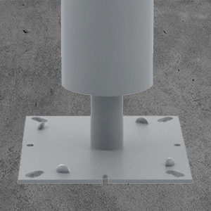
- Screw in the (4) 3 1/2” adjustment screws, 3/8” of an inch, into the 3/8” adjustment plate.
- Place the 3/8” adjustment plate on the end of the column, make sure the counter sunk holes are facing out. Align the Beam and adjustment plates so they are square. Using a 3/16” concrete drill bit, drill two holes 2 1/4” deep in the center of the two countersunk holes on the bottom side of the adjustment plate.
- Using the supplied Phillips head screws, fasten the screws into the two holes you just made.
- Use a pry bar or any lever, lift the column up to the beam where you fastened the two screws.
- Locate the screws in the large portion of the key hole. Slide the column over, locking the plate into place. Tighten the two screws then fasten the last two screws in the round holes in the Beam plate.
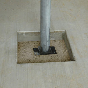
- Place the 1/4” bearing plate on the footing under the column. Loosely tighten the two adjustment screws into the 5/8” dimples. Use a level and plumb the column.
- Once the columns is plumb, use a 3/16” concrete drill bit and drill (4) 2 1/4” deep holes in each of the small sections of the key holes. Fasten the (4) hex head screws.
- Firmly tighten the adjustment screws in the 5/8” dimples. Once those are tightened, then screw in the last two into the threaded holes. Thread these screws down until you feel them hit the footing. Do not over tighten these screws.
- Fill in the gap between the bottom of the adjustment plate and bearing plate. If you are using this for new construction, the 4” slab will fill the gap. If you are using this for a remodel, box out the plates and fill with grout.
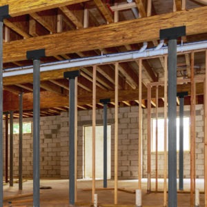
Column Installation:
Wooden Beam
- Measure the height from the bottom of the beam to the top of the footing. Be sure to subtract the thickness of the cap and base plates.
- Cut the column using a Column E-Z Cutter tool or equivalent. Do not cut the end with the embedded fastening unit. To cut, place the cutting wheel on your mark and tighten until the wheel is tight against the column. Start turning the tool around the column, slightly tightening the wheel during the turn. Once you have scored the column all the way through the steel, the concrete will break and you are left with a clean cut. If the concrete is not flush with the steel either use a hammer to get the concrete flush or use a small amount of concrete to fill the void.
- Install vertically.
- Cap plate must be bolted or nailed into the wooden beam. Cap plate must be attached to the column.
- Base plate should be fastened to the footing. Base plate should be attached to the column.
Steel Beam
- Measure the height from the bottom of the beam to the top of the footing. Be sure to subtract the thickness of the cap and base plates.
- Cut the column using a Column E-Z Cutter tool or equivalent. Do not cut the end with the embedded fastening unit. To cut, place the cutting wheel on your mark and tighten until the wheel is tight against the column. Start turning the tool around the column, slightly tightening the wheel during the turn. Once you have scored the column all the way through the steel, the concrete will break and you are left with a clean cut. If the concrete is not flush with the steel either use a hammer to get the concrete flush or use a small amount of concrete to fill the void.
- Install vertically.
- Cap plate must be bolted and/or welded to the steel beam. Cap plate must be attached to the column.
- Base plate should be fastened to the footing. Base plate should be attached to the column.